Electrode Roll Genealogy: How Key Reissue at Slitting and Stacking Shrinks Defect Isolation from 1,500 Cells to 2
Abstract
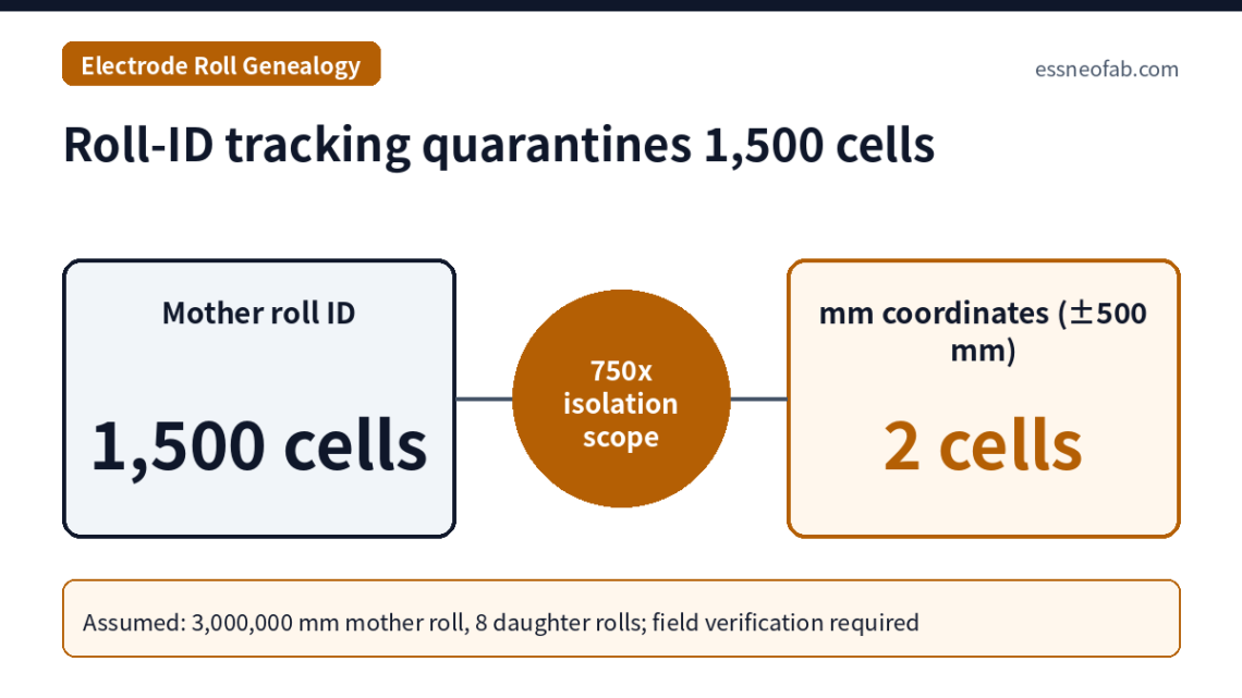
When traceability resolution in the electrode R2R section stops at the “roll ID,” a 5,000 mm coating defect in one mother roll expands the isolation scope to every cell derived from that mother roll. Assuming a 3,000,000 mm mother roll, 4 lanes, 8 daughter rolls, and 8,000 mm of cathode web per cell, the isolation scope is 1,500 cells at mother-roll-ID resolution, 188 cells at daughter-roll-ID resolution, and 2 cells at encoder-based mm-coordinate resolution (±500 mm), a difference of up to 750 times.
This resolution is preserved only when a key consisting of “parent ID + parent coordinate interval + direction bit + transform coefficient” is reissued at every split and merge point; if a field is missing at even one point, resolution collapses to that point’s parent unit. A missing direction bit in particular does not merely lower resolution but moves the isolation window to the mirror position, creating an escape path more dangerous than roll-ID tracking.
1. Conclusion First — The Weakest Reissue Point Sets Electrode Genealogy Resolution
The defect isolation scope of electrode roll genealogy[1] is determined not by the measurement precision of the coater, but by the resolution of whichever point among roll press, slitting, notching, and stacking has the least complete key reissue. Even if mm-level defect coordinates are captured at coating, the isolation scope reverts to the entire mother roll if the lane number and parent coordinate interval are not recorded at slitting.
Situation (S): A coated mother roll passes through the roll press and is divided at slitting into daughter rolls (pancakes)[2] by the number of lanes and length splits, cut into sheets at notching, and then cathode and anode are merged back into a single cell at stacking. Complication (C): Many lines pass roll IDs between processes via RFID tags on roll cores and similar means, and judge genealogy to be secured on that basis. Question (Q): With roll ID only, how much larger is the isolation scope when a defect occurs, compared with mm-coordinate tracking? Answer (A): Under these assumptions, 1,500 cells at mother-roll-ID resolution versus 2 cells at mm-coordinate resolution (±500 mm): 750 times.
The assumption this article refutes is that “genealogy is complete as long as the roll-ID links are unbroken.” Genealogy connectivity and resolution are separate properties, and it is the latter that determines isolation cost.
2. Mechanism — Key Reissue at Split and Merge Points
In the R2R[3] section, the coordinate system is reborn at every process. The length coordinate xM (mm) defined at coating is transformed at the roll press by elongation and head trim, the winding direction flips at every rewind, and slitting splits the web in the width direction (lanes) and length direction (segments). To answer downstream “where in the mother roll did this sheet come from,” each child key must be born carrying its transform relationship to the parent coordinate system.
IEC 62264-2 defines a material lot as a “uniquely identifiable amount of a material” and a material sublot as a “uniquely identifiable subset of a material lot.” A daughter roll corresponds to a sublot of the mother roll, but the standard’s lot–sublot relationship alone does not express which interval of the parent the sublot is. Interval information must be designed as a separate attribute.
| Point | Type | Key to reissue (mandatory fields) | Resolution if a field is missing |
|---|---|---|---|
| Coating | Origin creation (1→1) | Mother roll ID, length-coordinate origin, lane layout, defect coordinate xM (mm) | Without an origin, all subsequent mm coordinates are meaningless |
| Roll press | Coordinate transform (1→1) | Pressed-roll ID, parent ID, elongation correction coefficient, head trim offset (mm), direction bit | Missing correction → coordinate shift (elongation × position) |
| Slitting | Split (1→N) | Daughter roll ID, parent ID, lane number, parent coordinate interval [start, end] (mm), direction bit | Missing lane → entire mother roll / missing interval → entire lane |
| Notching | Split + splice[4] merge | Sheet sequence number ↔ daughter-roll coordinate interval, splice position (mm) | Unrecorded splice → originating daughter roll of boundary cells unknown |
| Stacking | Merge (cathode + anode → cell) | Cell ID ↔ {(daughter roll ID, coordinate interval)} for cathode and anode each | Missing interval → reverts to daughter-roll level |
The core of Table 1 is that every reissued key has the same four elements: parent ID · parent coordinate interval · direction bit · transform coefficient. The state in which only the parent ID is passed is what is commonly called “roll-ID tracking”: connectivity is complete, but resolution is the entire parent roll.
3. Assumed Scenario Calculation — Isolation Scope by Resolution
The calculation premises are as follows (all assumed). The cathode mother roll is 3,000,000 mm long, the coating width yields 4 lanes, and at slitting each lane is split in two lengthwise to make 8 daughter rolls (1,500,000 mm each). Notching sheet pitch is 200 mm and there are 40 cathode sheets per cell, so one cell consumes 8,000 mm of cathode web; one daughter roll corresponds to 187.5 cells and one mother roll to 1,500 cells. Cells are assumed to be 100 Ah·3.2 V (0.32 kWh).
The defect is a 5,000 mm coating anomaly detected in lane 2 at coating coordinates 600,000–605,000 mm. Coordinate uncertainty is compared at two levels: ±500 mm when encoder-based coordinates are used with trim and splice offsets recorded at each reissue, and ±2,000 mm when position is converted from inter-process timestamps (coating speed 60 m/min (1,000 mm/s) × clock synchronization error ±2 s). The isolation window is the defect length plus the uncertainty on both sides, and the number of cells touched is counted under the worst case (ceiling of window length ÷ web length per cell, + 1).
| Tracking resolution | Isolation window length | Isolated cells | Isolated energy | vs. mm coordinates (±500 mm) |
|---|---|---|---|---|
| Mother roll ID | 12,000,000 mm (sum of 4 lanes) | 1,500 cells | 480 kWh | 750× |
| Daughter roll ID (lane and segment identified) | 1,500,000 mm | 188 cells (arithmetic 187.5) | 60 kWh | approx. 94× |
| Timestamp-converted mm coordinates (±2,000 mm) | 9,000 mm | 3 cells | 0.96 kWh | 1.5× |
| Encoder mm coordinates (±500 mm) | 6,000 mm | 2 cells | 0.64 kWh | Reference |
| mm coordinates, direction bit missing | 6,000 mm (mirror position) | 2 cells wrongly isolated + defective cells escape | — | Isolation failure |
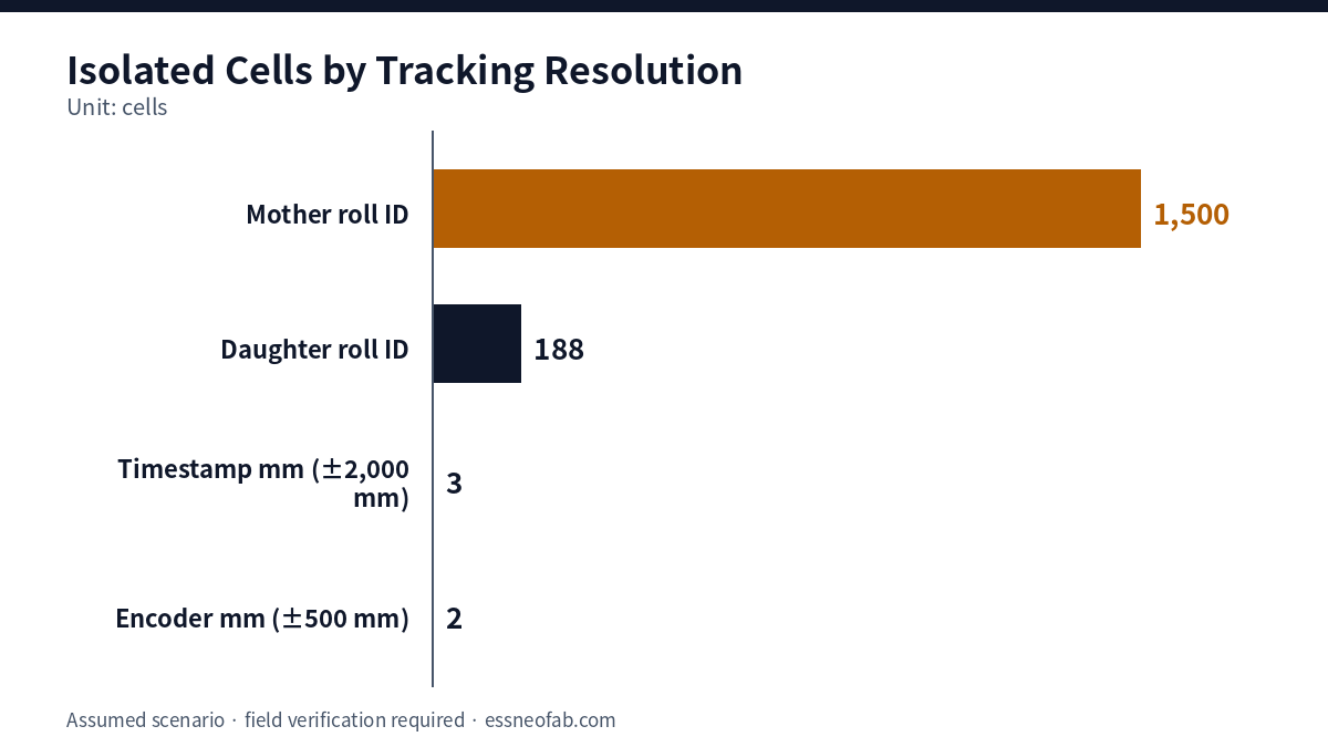
The 8-fold difference between rows 1 and 2 of Table 2 is obtained simply by reissuing two fields at slitting: lane number and segment interval. The roughly 94-fold difference between rows 2 and 4 is obtained by binding the daughter-roll coordinate interval to the cell ID at notching and stacking. Most of the reduction in isolation scope is thus achieved not by new measurement equipment but by a data-model change that adds fields to existing split and merge events.
Row 3 shows that the bottleneck of coordinate precision may be clock synchronization rather than sensors. In the timestamp-conversion method, a 1 s clock synchronization error becomes a 1,000 mm position error at a line speed of 60 m/min, so inter-process time-synchronization accuracy must be specified together with line speed.
4. Limits — Mis-isolation Caused by Direction Bits and Elongation Correction
Row 5 of Table 2 is this article’s most important observation. Assuming the winding direction flips at every rewind, a defect at coating coordinates 600,000–605,000 mm is interpreted at the mirror position of 895,000–900,000 mm in a daughter-roll coordinate system missing its direction bit. In that case the system precisely isolates 2 cells unrelated to the defect and ships the actual defective cells as good. Roll-ID tracking merely over-isolates conservatively and creates no escapes, so mm tracking without direction information is more dangerous than roll-ID tracking.
Elongation correction has the same structure. Assuming a roll-press elongation of 1.0%, the point at coating coordinate 600,000 mm shifts by about 6,000 mm after pressing, which exceeds the ±500 mm uncertainty on either side of the isolation window. Actual elongation varies by equipment and electrode specification and requires measurement, and the correction coefficient must be included in the reissued key for each roll. The elongation behavior inside the unit equipment itself is outside this article’s scope and requires separate review.
This differs from the article on where cell traceability breaks at the line level. That article dealt in general terms with where cell-history binding breaks; this one addresses which fields a key must carry when reissued so that resolution is preserved while 1→N splits and N→1 merges repeat in the continuous-web section before a cell ID is assigned. The role of inter-process inventory in absorbing quarantined daughter rolls and cells connects to the perspective of inter-process buffers.
5. Conclusions and Implications
Electrode genealogy cannot be evaluated by connectivity alone; a resolution audit at each split and merge point is required. Under these assumptions, the isolation scope spans 750 times, from 1,500 cells at mother-roll-ID resolution to 2 cells at encoder mm coordinates, and most of that reduction is achieved through data-model changes: lane and interval fields at slitting and coordinate-interval binding at stacking.
The proposed target specification is 100% recording of the four-element key (parent ID, parent coordinate interval, direction bit, transform coefficient) at every reissue point, cell-level coordinate uncertainty of ±500 mm or less, and inter-process time-synchronization error of 0.1 s or less. These are arbitrarily set values based on this assumed scenario; pilot-line results are not applied 1:1 to mass-production lines, and further verification is required.
FAQ
Q. Coating defects are marked by the coater’s inline inspection and automatically ejected at notching, so isn’t low genealogy resolution harmless?
A. Defects detected by inline inspection can be handled that way. Genealogy resolution matters when the cause interval must be traced backward after the fact, at formation and inspection after cell assembly or in the field, where by premise there was no defect mark at the time of detection. What determines the isolation scope of retrospective tracing is not the inline ejection function but the resolution of the reissued keys.
Q. If a code is marked directly on every electrode sheet, isn’t key-reissue design unnecessary?
A. Sheet-level marking greatly increases resolution after notching, but the coordinate-transform problem in the section before marking (coating to slitting) remains. There are studies of marking at the coating stage, but marking position, read rate, and process-interference conditions differ by line, so further verification is required for mass-production application.
Field Application Notes
Items executable first thing Monday morning.
| Check | How to execute | Notes |
|---|---|---|
| ☐ Audit fields at reissue points | Check, in the Table 1 format, whether each event record at coating, roll press, slitting, notching, and stacking carries the four-element key | If even one is missing, that point is the resolution ceiling |
| ☐ Direction-bit verification test | Place a test mark at a reference coordinate during coating and compare the detected position at notching with the MES-converted position | If it appears at the mirror position, review isolation logic immediately |
| ☐ Measure elongation correction coefficients | Record roll length before and after the roll press for each roll and compute the coefficient distribution (mean, standard deviation) | Record sample roll count and temperature/humidity conditions |
| ☐ Check inter-process time synchronization | Measure clock offset between coater and notcher controllers and convert to position error (mm) using line speed (m/min) | Prioritize lines using timestamp conversion |
| ☐ Isolation drill | Select one past defect, compute the number of isolated cells with the current system, and compare with the resolution levels in Table 2 | Also record the time (s) taken to compute it |
Footnotes
[1] Roll Genealogy: A data structure recording the split and merge history of electrode rolls as parent–child relationships, enabling backward tracing from any cell to the original mother roll and the position within it.
[2] Daughter Roll (Pancake): A narrow roll split from the mother roll at slitting and newly wound.
[3] R2R (Roll-to-Roll): A process method that continuously processes material in continuous-web form while unwinding and rewinding it.
[4] Splice: A joint connecting the end of a preceding roll to the start of a following roll to maintain continuous feed.
Sources: IEC, “IEC 62264-2:2013 Enterprise-control system integration — Part 2” sample (definitions 3.1.5 material lot, 3.1.7 material sublot), https://cdn.standards.iteh.ai/samples/16716/96db6d02f14e4980a49304902050b913/IEC-62264-2-2013.pdf / IEC, “IEC 62264-2:2026” (edition 3.0, 2026-03-06; whether the new edition retains the same definitions requires confirmation), https://webstore.iec.ch/en/publication/75127 / Design World, “Lithium Ion Battery Manufacturing – RFID is on a Roll”, 2023-05-02, https://www.designworldonline.com/lithium-ion-battery-manufacturing-rfid-is-on-a-roll/ / Sommer et al., “Marking of Electrode Sheets in the Production of Lithium-Ion Cells as an Enabler for Tracking and Tracing”, Procedia CIRP 104, 2021, https://www.sciencedirect.com/science/article/pii/S2212827121010684 / Sommer et al., “Integration of an Electrode-Sheet-Based Traceability System into the Manufacturing Process of Lithium-Ion Battery Cells”, Energy Technology, 2024, https://onlinelibrary.wiley.com/doi/full/10.1002/ente.202301221 / Lindenblatt et al., “Image-matching in electrode production of lithium-ion batteries for marker-free tracking and tracing applications”, Future Batteries 5, 2025, https://www.sciencedirect.com/science/article/pii/S2950264025000280
Measurement & Calculation Conditions: Mother roll 3,000,000 mm, 4 lanes × 2 length splits (8 daughter rolls, 1,500,000 mm each), sheet pitch 200 mm, 40 cathode sheets per cell (8,000 mm of web), cell 100 Ah·3.2 V, defect length 5,000 mm (lane 2, coating coordinates 600,000–605,000 mm), coordinate uncertainty ±500 mm (encoder) and ±2,000 mm (coating speed 60 m/min × clock synchronization error ±2 s), direction reversal at every rewind, and roll-press elongation of 1.0% are all assumed values. Head/tail trim and defect propagation on the anode side are excluded. Field verification is required.