The Interface Between Laser Notching Cycle Time and Line Takt Time — The Head-Count Sizing Problem Revealed by DI ENT’s Ohio Supply Contract
Abstract
DI ENT signed laser notching1 equipment supply contracts worth a combined KRW 87.3 billion, across two separate orders, with LH Battery Company (an LG Energy Solution–Honda joint venture), for delivery to Honda’s new second battery plant in Ohio, USA, by March 2026. This supply contract is more than an order-win announcement — it surfaces an interface-design problem between the notching process’s cycle time2 and the line’s takt time3. When the processing time of a single notching head is longer than the takt time the line requires, adding parallel heads becomes unavoidable, and as burr4-width specifications are tightened, per-head processing time increases, causing the required head count to rise non-linearly. This article quantifies the head-count sizing formula and its sensitivity through an assumed scenario, and separately flags items that require empirical verification.
1. The Question Raised by the Ohio Supply Contract — How Many Notching Heads Are Needed
To state the conclusion first: the number of laser notching units supplied is not determined by the contract value or the equipment spec sheet alone. If the time required for one notching head to process a single electrode sheet (head cycle time) is longer than the takt time the line requires, the line must deploy multiple heads in parallel to bring the effective processing speed below the takt time.
Situation: DI ENT agreed to supply laser notching equipment to LH Battery Company’s new Ohio plant by March 2026. Complication: the supply-contract announcement disclosed neither the line’s target production capacity, cell specifications, nor the notching head specifications — this is information shared only between the equipment supplier and the ordering company, leaving outsiders unable to answer the question of “how many units are needed.” Question: on what basis, then, does a line designer size the number of notching heads? Answer: the required head count must be back-calculated from the ratio of head cycle time to line takt time, reflecting the trade-off that burr quality specifications impose on head cycle time.
2. Mechanism — Head Cycle Time versus Line Takt Time
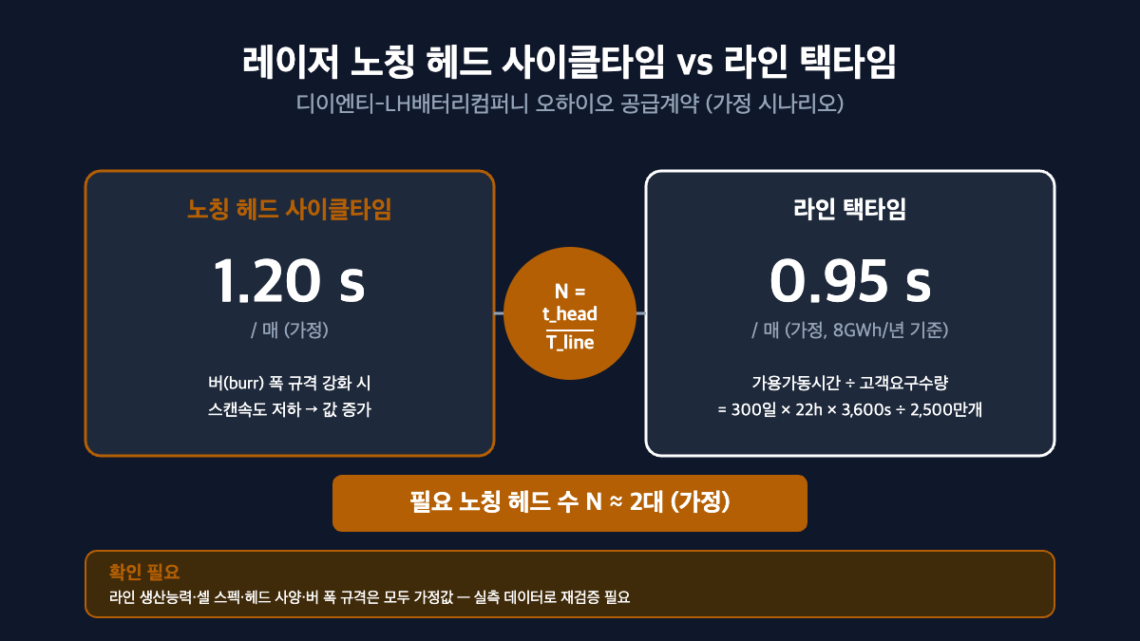
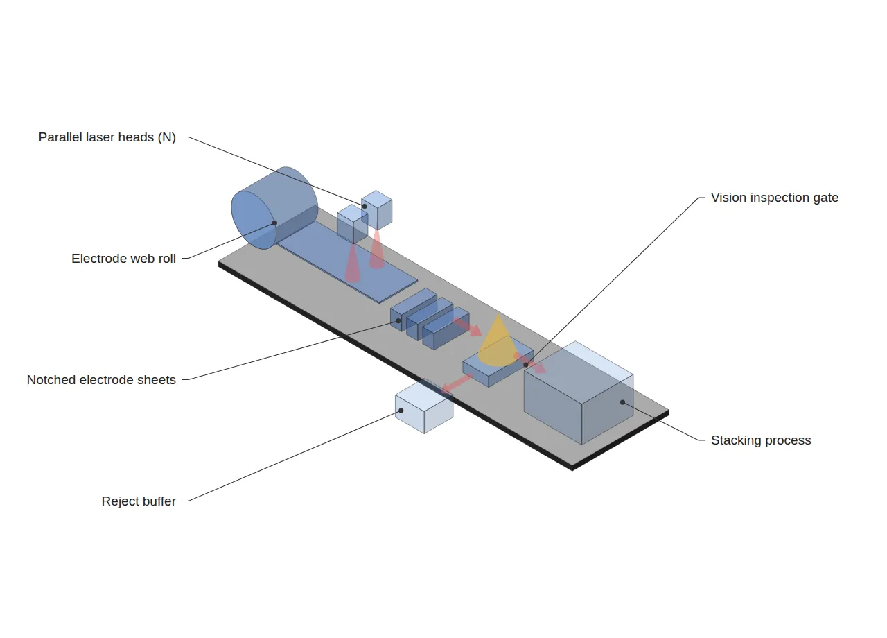
The notching process continuously cuts and separates individual electrode sheets from the electrode web. If the time required for one laser head to process a single electrode sheet is defined as the head cycle time (t_head), then deploying N heads in parallel gives an effective cycle time of t_head/N. This value must be less than or equal to the line takt time (T_line) for the notching process not to become a bottleneck.
The required head count is sized using the following formula.
N ≥ t_head / T_line
Here, the line takt time (T_line) is a value back-calculated from OEE5 and the production target. The following is a scenario with assumed values explicitly flagged as requiring confirmation.
| Variable | Assumed Value | Note |
|---|---|---|
| Line annual production capacity | 8 GWh/yr (assumed) | Confirmation needed — Ohio plant’s official target not disclosed |
| Cell spec | 100 Ah × 3.2 V = 320 Wh/cell (assumed) | Confirmation needed — pouch/prismatic format not disclosed |
| Operating conditions | 300 days/yr × 2 shifts × 22 h/day (assumed) | Applying existing industry-standard convention |
| Required cell count | 25,000,000 units/yr | 8×10⁹ Wh ÷ 320 Wh |
| Annual operating time | 23,760,000 s | 300 days × 22 h × 3,600 s |
| Line takt time (T_line) | 0.95 s/sheet (assumed) | Simplified per-sheet basis — actually needs further breakdown by stack count (confirmation needed) |
| Head cycle time (t_head, standard scan) | 1.20 s/sheet (assumed) | Based on laser scan speed |
| Required head count (N) | 2 units | N = 1.20/0.95 = 1.26 → rounded up |
Tightening the burr-width specification (for example, lowering the target burr width to 0.025 mm or less) requires slowing the laser scan speed, which increases head cycle time. If t_head is assumed to increase to 1.50 s/sheet under this condition, N = 1.50/0.95 = 1.58 → still rounds up to 2 units, but the per-head margin (buffer) shrinks considerably. The sensitivity is expressed as follows.
∂N/∂t_head = 1/T_line ≈ 1.05 (heads/s)
In other words, for every 1-second increase in head cycle time, the required head count increases by approximately 1.05 units. This trade-off between burr quality specification and processing speed is the substantive variable that determines whether notching heads must be added, and it is not revealed by the contract value or delivery schedule alone.
3. Basis — DI ENT’s Contract and Prior Patents
DI ENT stated that, in addition to its existing laser notching equipment, it is newly adding a “press” equipment lineup. This can be interpreted as a strategy to manage the interface with post-notching processes (stacking, pressing) in an integrated manner within its own equipment portfolio. Below are prior patents related to laser notching and burr management; no patent matching the DI ENT–LH Battery Company contract on a 1:1 basis was confirmed, and these are cited only as general prior-art references for the process.
| Publication No. | Title | Relevant Content |
|---|---|---|
| KR20200133942A | Electrode notching device | Defines burr as residual electrode-body/active-material matter left on the cut surface |
| KR101700113B1 | Electrode Notching Processing Apparatus for Electrode of Secondary Battery | Addresses cutting defects caused by foreign matter/vibration at the tab area |
| KR102181983B1 | Laser notching device | Basic structure of a laser notching device for electrode film |
| US11594713B2 | Notching apparatus and method for secondary battery | Reduces defect rate through process-time reduction and drying-efficiency improvement |
Burr defects do not end within the notching process itself. Residue remaining on the cut surface can lead to downstream stacking-alignment defects or internal short-circuit risk, so if the reject rate rises at the vision-inspection gate immediately after notching, the Quality component of the line’s overall OEE degrades. In other words, sizing the notching head count is not simply a processing-speed problem — it is an interface problem that must be examined together with the reject-buffer design of the downstream quality gate.
4. Trend Snapshot
Of the related developments confirmed this week, here are two brief items worth noting, though not directly connected to this article’s main subject matter.
- India’s Central Electricity Authority (CEA) published a draft comprehensive overhaul of grid-interconnection technical standards for BESS, renewable energy, and pumped hydro at 33 kV and above (comment period through 2026-09-02). Around the same time, IEEE 2800.2-2026 (recommended IBR grid-interconnection test and verification procedures) was also published — separately from the domestic ESS grid-connection queue issue (Re-Reading the ESS Grid-Interconnection Queue in the Language of Line Balancing), overseas grid-interconnection technical standards are being rapidly revised.
- Solid-state battery pilot-line status was updated simultaneously across several companies: QuantumScape’s “Eagle Line” (completed 2026-02-04), and domestically SK On (Daejeon, targeting 2029), Samsung SDI (Suwon S-Line, targeting 2027), LG Energy Solution (under construction at Ochang), and Hyundai Motor (running its own pilot) — each on a different schedule. However, industry-wide, the first-pass yield (FPY) of sulfide-based pilot lines remains below 70%, still some distance from the commercialization benchmark of 95% or higher.
5. Conclusion and Implications
What the DI ENT–LH Battery Company contract shows is not the notching-equipment supply itself, but the question of how to design the interface between notching cycle time and line takt time. The head-count sizing formula (N ≥ t_head/T_line) and sensitivity (∂N/∂t_head ≈ 1.05) presented in this article are both based on a scenario in which line production capacity, cell specification, and operating conditions are arbitrarily assumed. Because the actual Ohio plant’s line specifications, notching head specifications, and burr-width specification have not been disclosed, the figures above should be used only as an estimation basis, and require re-verification once empirical data is obtained.
FAQ
Q. Doesn’t simply adding more notching heads always resolve the bottleneck?
A. No. Even if adding heads lowers the effective cycle time, if the takt time of the downstream stacking/inspection gate remains unchanged, the bottleneck simply shifts. Furthermore, greater alignment error between heads can make burr quality less uniform — so adding heads is meaningful only when the entire downstream interface is redesigned together.
Field Application Notes
| Check Item | Verification Method | Note |
|---|---|---|
| Recalculate line takt time | Re-derive T_line from actual line production target, cell spec, and operating hours | Needs to replace this article’s assumed value (0.95 s/sheet) |
| Measure head cycle time | Obtain per-head processing time (by scan-speed condition) from the supplier’s spec sheet | Request separate values by burr-width specification |
| Finalize burr-width specification | Set target burr width (mm) against the alignment tolerance of the downstream stacking process | Confirmation needed — this article’s 0.025 mm is an assumed value |
| Check reject-buffer capacity | Confirm the reject rate at the vision-inspection gate immediately after notching and the buffer inventory margin | Manage in conjunction with the OEE quality component |
1 Notching: The process of cutting and separating individual electrode sheets from the electrode web.
2 Cycle Time: The time required for one unit of equipment (or one head) to process one unit of product (or one sheet). Must not be used interchangeably with takt time.
3 Takt Time = Available Operating Time ÷ Customer Required Quantity.
4 Burr: Residual electrode-body/active-material matter left on the laser-cut surface.
5 OEE = Availability × Performance × Quality.


One Comment
Pingback: