Introducing Robotic Automation Equipment — Where Does the Interface with Line Takt Time Break Down
Abstract
Abstract. The supply contract disclosed by JS Robotics on September 2, 2026, worth roughly KRW 33.26 billion, for battery-manufacturing robotic automation equipment brings renewed attention to the Cycle Time1-Takt Time2 gap that arises the moment new robotic equipment is connected to an existing R2R (Roll-to-Roll) line. This article calculates an assumed scenario in which one cycle of robotic automation equipment exceeds the line takt time, distinguishing the range of variation that buffer3 accumulation design can absorb from the structural gap it cannot. The analysis concludes that buffers absorb only micro-stop-level variation, and that a structural gap where the robot’s own cycle time exceeds takt time translates directly into OEE4 performance-factor loss, requiring a review of robot specification/layout rather than buffer expansion. As this is a calculated scenario rather than lab/pilot verification, re-verification against actual measured robot cycle time is essential upon real deployment.
1. Introducing Robotic Automation Equipment – Where Does the Interface with Takt Time Break Down
To state the conclusion first: the variable that must be checked first in practice when integrating robotic automation equipment into an existing R2R line is whether the robot’s rated cycle time is at or below the line takt time. If this check is skipped, no amount of increasing buffer slots resolves the resulting OEE performance-factor loss. This is a case in which the basic line-design principle that a buffer is a “temporary variation absorber,” not a “structural throughput-gap resolver,” is reconfirmed during robot integration.
(Situation) On September 2, 2026, JS Robotics disclosed a contract to supply robotic automation equipment for secondary-battery manufacturing processes to an overseas customer, worth roughly KRW 33.26 billion. The contract period runs from September 1, 2026 to August 31, 2027, and the counterparty is undisclosed for trade-secret reasons. (Complication) However, the disclosure contains no information on the robot’s rated cycle time, the target line’s takt time, or the buffer design specification between the two values. (Question) When robotic automation equipment is connected to an existing line, how does this gap actually affect the line’s overall throughput? (Answer) This article sets a target specification as an assumed scenario and verifies the issue with concrete figures.
2. Trends in Robotic Automation Equipment Adoption on Secondary-Battery R2R Lines
JS Robotics (formerly JS Tech) declared in March 2026, when it changed its name, a shift from a semiconductor-equipment focus to a robotic automation business spanning bio, secondary batteries, and other industries. This supply contract equals 108.48% of the company’s immediately preceding annual revenue (KRW 30.661 billion), showing that demand for robotic automation in secondary-battery manufacturing processes has grown large enough to shift individual equipment makers’ revenue structures.
During the same period, PNT expanded its electrode-process equipment orders in India, growing its first-half order backlog to roughly KRW 1.5 trillion, with Tata Group affiliate Agratas identified as a new customer. By contrast, looking at 2025 results for 31 battery equipment companies, only 6 saw revenue growth while 25 saw declines, making it clear that line-automation investment is concentrating in specific processes and specific customers rather than spreading across the industry as a whole. It is worth noting, from a practical standpoint, that the more robotic automation orders increase, the greater the risk that verifying the robot-line interface design’s consistency at the individual-line level gets deprioritized.
3. Cycle Time-Takt Time Interface Calculation Scenario
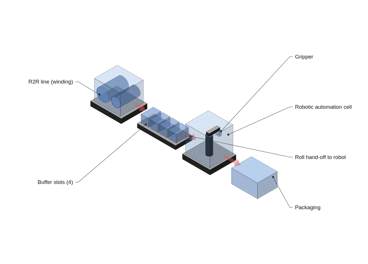
Verification needed: the figures below are not disclosed contract specifications, but a target scenario arbitrarily set by essneofab assuming a situation where robotic automation equipment is integrated at the back end of an existing R2R line (the winding-packaging interface). Actual robot cycle time and line takt time vary by equipment and contract, so the calculation below is a reference value intended to illustrate interface-design logic, and field verification is essential.
| Variable | Value (assumed) | Basis |
|---|---|---|
| Customer required quantity | 1,200 rolls/day | Assuming 3 shifts |
| Available operating time | 72,000 s/day (20 h) | Assuming 83.3% operating rate |
| Takt time | 60 s/roll | 72,000 s / 1,200 rolls |
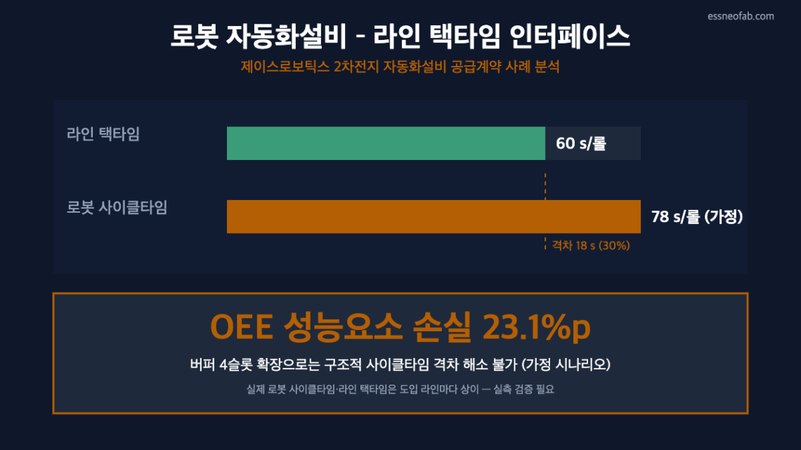
| Robotic automation equipment cycle time | 78 s/roll | Assumed (contract spec undisclosed) |
| Actual achievable throughput | 923 rolls/day | 72,000 s / 78 s (-23.1% vs. target) |
| OEE performance-factor loss | 23.1 pp | 1 – (60/78) |
Whether buffer design can absorb this gap must be separately verified. Assuming gripping-failure retries and other micro-stops occur 4 times per hour at an average of 32 s each, total stoppage time per hour is 128 s; converting this against the takt time (60 s) gives a required buffer slot count of 128/60 approx. 2.13, or about 4 slots including a safety margin.
However, this buffer only absorbs momentary, probabilistic delays like micro-stops; it cannot absorb the gap itself where the robot cycle time (78 s) structurally exceeds takt time (60 s) by 18 s (30%). No matter how many buffer slots are added, the upper bound of what the robot can process is 60,000/78 s per hour, so the line’s overall throughput ultimately remains dependent on the robot cycle time.
The implication drawn from this assumed scenario, then, is that during the robotic automation equipment specification review stage, one should first confirm whether the rated cycle time is at or below takt time, and if it exceeds it, the approach should be to shorten the cycle time itself – via parallel robot deployment (splitting across 2 units) or adopting a dual gripper5 – rather than expanding the buffer. This conclusion is based on a calculated scenario; on an actual deployment line, the buffer/parallelization decision must be reconfirmed after cross-verifying the robot vendor’s measured cycle time against the line takt time.
4. Trend Snapshot
L&F’s LFP-dedicated subsidiary L&F Plus has completed a plant at the Phase 2 site of the Dalseong-gun national industrial complex in Daegu and will begin mass production of LFP cathode material at an annual rate of 30,000 tons in late Q3 2026 (targeting 60,000 tons total by H1 2027, with an investment of KRW 338.2 billion). This is a separate new-line startup matter from (an earlier article) that addressed the compaction density-calendering interface discussed in Section 3 above, and whether robot/automation-equipment interface verification accompanies the early ramp-up of this line requires separate confirmation.
On the patent-statistics front, solid-state battery patent filings by Korean-nationality applicants grew from 45 in 2004 to 1,044 in 2023, a compound annual growth rate of 18%, the world’s second-highest growth rate after China (33.6%). Over the most recent 3 years (2021-2023), Samsung SDI (51.7%) and LG Energy Solution (50.8%) ranked first and second in growth rate, showing that material/cell-level patent competition is accelerating along an axis separate from line-automation investment.
5. Conclusion and Implications
Introducing robotic automation equipment cannot be judged on the individual robot’s performance specification alone; it must always be verified in relation to the takt time of the line it connects to. This article’s calculated scenario showed that when cycle time exceeds takt time by 30%, buffer-slot expansion alone cannot resolve a 23.1 pp OEE performance-factor loss. This is also consistent with the principle common to prior art identified here – a robot-conveyor synchronization patent (EP1110854B1) and a buffering conveyor patent (US12059803B2) – namely that the throughput rates of the two systems being synchronized must fundamentally match.
Patents on battery-module gripping/docking (US20160368464A1), gripper insertion-force control (EP2932552A1), and transfer-robot battery loading/unloading (WO2021227993A1) address the precision of the robot-material contact interface, but these too are valid only on the premise that the robot’s own cycle time is consistent with the upstream process takt time. Line designers must always confirm the rated cycle time in the robot vendor’s specification sheet, secure a margin against takt time (ideally 10-15% or more), and design the buffer as a supplementary measure only once that margin is in place.
FAQ
Q. If buffer slots are increased sufficiently, won’t the robot cycle-time-excess problem eventually be resolved as well?
A. No. Because a buffer is a finite storage space, if the cycle-time gap persists structurally, the buffer eventually fills and the entire line becomes dependent on the robot’s processing rate. A buffer can only absorb probabilistic, momentary variation like micro-stops – the same basic premise as queueing theory (if the arrival rate continuously exceeds the service rate, the queue diverges).
Field Application Notes
| Check item | How to execute | Standard |
|---|---|---|
| Confirm robot rated cycle time | Request vendor spec sheet / FAT measured data | Secure a margin of 10-15% or more against takt time |
| Recalculate takt time | Recompute as available operating time / customer required quantity | Observe the fixed definition (do not conflate with cycle time) |
| Collect micro-stop history | Collect stoppage logs for 1 week or more and calculate frequency and average duration | Buffer slot count = (frequency x average stop time) / takt time, with safety margin applied |
| Determine whether the gap is structural | Observe continuously for 30+ minutes whether cycle time > takt time persists | If persistent, consider robot parallelization or a dual gripper instead of buffer expansion |
Footnotes
1. Cycle Time: the actual time required for one piece of equipment to process one unit of product.
2. Takt Time: available operating time divided by customer required quantity – the maximum processing time per unit allowed to meet customer demand. Not used interchangeably with cycle time.
3. Buffer: temporary inventory/holding space to absorb processing-speed differences between processes.
4. OEE (Overall Equipment Effectiveness): overall equipment efficiency calculated as Availability x Performance x Quality.
5. Gripper: the end effector at the tip of a robot arm that grips and transfers an object.


You May Also Like
Embedding an AI Vision Inspection Gate in the Line: Redefining OEE and Takt-Time Design Variables
Designing the Merge Point in a 10 GWh Pack-Container Integration Line: Synchronizing Two Upstream Lines and Sizing AGV Fleet from the Powertrac × Sunka Lead Order