LFP High-Compaction-Density Conversion and the Calendering Interface: How Nip Pressure and Line Speed Affect Takt Time
Abstract
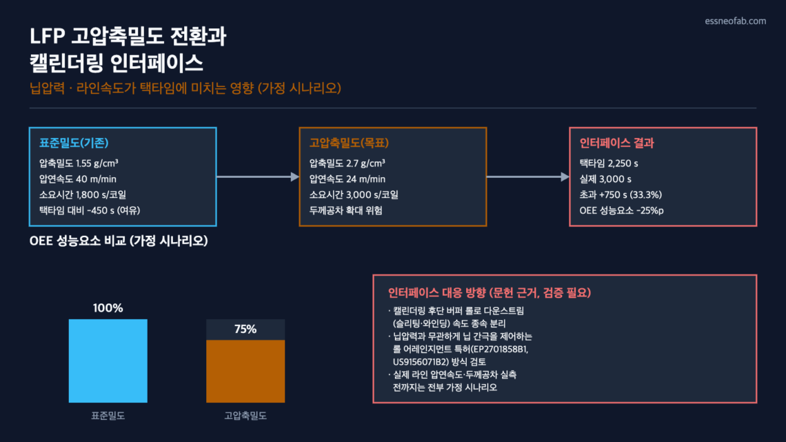
If the compaction density target for LFP (Lithium Iron Phosphate) cathode material — typically in the 1.4–1.6 g/cm³ range — is raised to the 2.7 g/cm³ class that L&F has disclosed as its end-2026 mass-production target, the nip pressure and line speed of the calendering (rolling) process must be redesigned, and this directly affects the takt time and OEE (Overall Equipment Effectiveness) performance factor of existing operating lines.
In an assumed-scenario calculation, if the rolling speed decelerates from 40 m/min to 24 m/min, the calendering time per coil (1,200 m) increases from 1,800 s to 3,000 s, creating a bottleneck that exceeds the 2,250 s takt time by 750 s (33.3%). The thickness-tolerance widening that accompanies increased nip pressure (assumed: 300 kN/m → 480 kN/m) could lead to a decline in the OEE quality factor, but this can be mitigated by reflecting, in the interface design, the approach of roll-press patents (EP3460881B1, US12288864B2, WO2022108202A1, EP2701858B1, US9156071B2) that control the nip gap independently of rolling load.
However, this calculation is entirely an assumed scenario, since beyond the disclosed target compaction density (L&F’s 2.7 g/cm³ class), the actual line’s rolling speed, nip pressure, and thickness-tolerance specifications have not been confirmed; field measurement verification is essential before application to an actual line.
1. Conclusion: Raising Compaction Density Is Not a Material-Spec Issue — It Is a Calendering-Interface Redesign Problem
The 2.7 g/cm³-class high-compaction-density LFP cathode material that L&F disclosed with an end-2026 mass-production target[1] is reported as a materials-side achievement of improved cell energy density. However, from a line-system perspective, this change simultaneously shakes two interface variables in the calendering process: nip pressure and line speed (m/min).
Situation: LFP cathode material has conventionally been designed with a low compaction density of 1.4–1.6 g/cm³ to secure long-cycle-life characteristics. Complication: raising compaction density to the 2.7 g/cm³ class requires either greater rolling load or longer rolling dwell time in the calendering process, which conflicts with existing line-speed conditions. Question: to what extent does this change affect the takt time and OEE of an existing operating line, and what interface design can mitigate it? Answer: in the range where rolling-speed deceleration is unavoidable, calendering becomes the line bottleneck and exceeds takt time; introducing an interface that controls the nip gap independently of rolling load is a realistic path to suppressing the quality-factor decline.
2. Process-Variable Comparison: Standard Density vs. High Compaction Density (Assumed Scenario)
The only disclosed figure is the target compaction density (2.7 g/cm³ class); the actual line’s rolling speed, nip pressure, and thickness tolerance have not been disclosed by L&F. The table below is an assumed scenario set by essneofab with reference to general literature ranges (calculation basis [2]), not measured values.
| Category | Standard Density (Existing) | High Compaction Density (Target, Assumed Scenario) | Change |
|---|---|---|---|
| Compaction density | 1.55 g/cm³ (confirmed: literature-range midpoint 1.4–1.6) | 2.7 g/cm³ (confirmed: L&F disclosed target) | +74.2% |
| Rolling speed | 40 m/min (assumed) | 24 m/min (assumed) | -40% |
| Nip pressure | 300 kN/m (assumed) | 480 kN/m (assumed) | +60% |
| Thickness tolerance | ±0.0030 mm (assumed) | ±0.0045 mm (assumed, if unaddressed) | +50% |
The literature reports that in the low-speed range of 5 m/min or below, calendering speed has a negligible effect on electrochemical performance[2]. However, this is an observation in the low-speed region, and measured data for deceleration aimed at securing rolling dwell time to achieve high compaction density (the 40→24 m/min in the table above) is not found within the range of public materials essneofab has confirmed — verification needed.
3. Estimating the Interface Impact: Takt Time and OEE Calculation (Assumed Scenario)
OEE = Availability × Performance × Quality; Takt Time = Available Operating Time / Customer Required Quantity (essneofab’s fixed definitions, not used interchangeably with Cycle Time or FPY). The calculation conditions are assumed as follows: of one 8-hour shift (28,800 s), available operating time is 27,000 s after excluding 1,800 s for CIP/inspection; customer required quantity is 12 coils/shift; web length per coil is 1,200 m (all assumed values; measurement-condition note: this is an essneofab-calculated scenario, not measured data from a specific line).
| Item | Formula | Result |
|---|---|---|
| Takt time | 27,000 s / 12 coils | 2,250 s/coil |
| Standard-density calendering actual time | 1,200 m / 40 m/min | 1,800 s (-450 s vs. takt time, 20.0% margin) |
| High-compaction-density calendering actual time | 1,200 m / 24 m/min | 3,000 s (+750 s vs. takt time, 33.3% excess) |
| OEE performance-factor impact | Theoretical cycle time (2,250 s) / Actual cycle time (3,000 s) | 0.75 (25 pp decline, assumed scenario) |
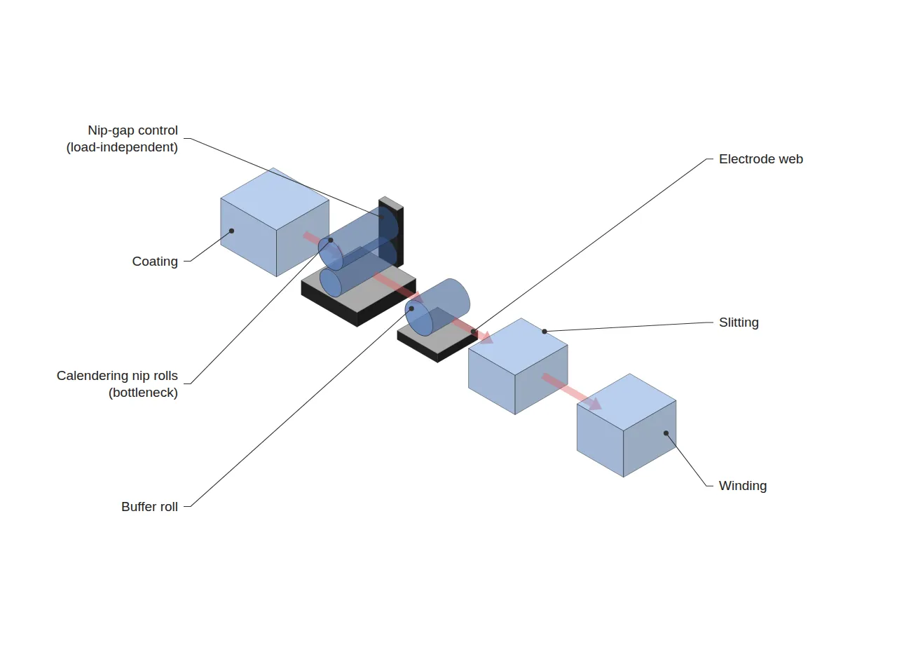
In this scenario, calendering shifts to become the line’s bottleneck process relative to coating, slitting, and winding. From a line-balancing perspective, the spare capacity of the coating and slitting processes goes to waste as-is; placing a buffer roll after calendering to absorb acceleration/deceleration, so that downstream slitting and winding are not directly dependent on calendering speed, is the direction that prevents a decline in overall line availability.
On the quality-factor side, the increase in nip pressure (300→480 kN/m, assumed) risks widening thickness non-uniformity across the web width. EP2701858B1 and US9156071B2 disclose a device that keeps the nip gap uniform independently of the rolling load (line load), explicitly naming “production of electrode material densified by rolls” as the target problem[3][4]. Reflecting this nip-gap-independent control approach in the interface leaves room to keep the thickness tolerance close to the standard level (±0.0030 mm) even as nip pressure rises — however, this is a directional suggestion based on the general disclosure content of the patent literature, and separate verification is required upon actual adoption.
4. Trend Snapshot
The following two items differ in mechanism from this article’s main subject (the calendering interface), so they are cited only briefly.
- Domestic distribution-grid ESS deployment-support project launched (2026-07-10, Ministry of Climate, Energy and Environment): nine Virtual Power Plant (VPP) operators will build a total of 128 MW/640 MWh of distribution-grid ESS, supporting an additional 182.4 MW of solar interconnection in grid-constrained renewable-energy regions such as Jeonbuk. KRW 558.6 billion in national funding is planned for 2026–2030.
- Cognex Korea on-device edge-AI vision new products: two new products that implement deep-learning inspection directly at the edge, without an external PC or separate GPU server, unveiled at Industrial AX Korea 2026.
5. Recommendation
Introducing high-compaction-density cathode material does not end with a materials-spec change. Without pre-recalculating the interface variables of calendering nip pressure and line speed, the line may face an unannounced increase in overall takt time at the moment the new material is introduced. A design direction that separately controls rolling load and nip gap is confirmed in the literature, but the actual line’s rolling-speed and thickness-tolerance targets are not specified within the range of public materials essneofab has confirmed, so all figures in this article are limited to an assumed scenario pending verification.
FAQ
Q. Does raising compaction density always slow down line speed?
A. Not necessarily. Rolling speed is one of several variables in combination with nip pressure, roll diameter, roll temperature, and number of passes; the 40→24 m/min deceleration in this article is an assumed-scenario value set by essneofab. On an actual line, alternatives such as raising roll temperature instead of nip pressure, or using multi-pass rolling, could also be considered to reduce the extent of the speed decline. L&F’s actual line parameters are not confirmed within the scope of the information provided, and further verification is needed.
Field Application Notes
| Check item | How to verify | Done |
|---|---|---|
| Obtain measured rolling speed (m/min) / nip pressure (kN/m) for the current line | Check calendering equipment HMI logs or maintenance history | ☐ |
| Recalculate per-coil time upon high-compaction-density target adoption | Substitute measured line speed into the Section 3 formula | ☐ |
| Confirm spare capacity of the buffer roll after calendering | Check whether slitting/winding equipment speed is dependent | ☐ |
| Review adoption of nip-gap-independent control | Compare EP2701858B1/US9156071B2 disclosed approach against current equipment spec | ☐ |
| Recalculate quality factor using measured thickness-tolerance data | Measure width-direction thickness profile during high-compaction-density trial run | ☐ |
References
[1] The Elec, “L&F to Mass-Produce High-Compaction-Density LFP to Compete with China by End of 2026,” thelec.kr
[2] Characterization of the calendering process for compaction of electrodes for lithium-ion batteries, ScienceDirect (reference for general process-variable ranges)
[3] EP2701858B1 — Roll arrangement having a device for regulating the roll nip, and method for regulating the roll nip in a roll arrangement
[4] US9156071B2 — Roll nip regulation device and method
Related patents: EP3460881B1 (Roll press machine with wrinkle prevention device), US12288864B2 (Electrode rolling apparatus and electrode rolling method), WO2022108202A1 (Electrode rolling apparatus and electrode rolling method)
Related Reading
- Converting EV Lines to ESS: Where Does OEE Break Down?
- Dry Electrode: Where Does the Line Bottleneck Move?
- The Interface Between Laser Notching Cycle Time and Line Takt Time — The Head-Count Sizing Problem Revealed by DI ENT’s Ohio Supply Contract


You May Also Like
Formation Channel Sizing Read from a Cell Assembly Equipment FAT — How 1 Second of Takt Time Moves 3,350 Channels
SK On’s Dual-Site ESS Production Bases — Where Fixed Contracts and Variable Bidding Split Takt Time Design
One Comment
Pingback: