46-Phi Cylindrical Cell Line Conversion: The Pressure-Sensor–BMS Interface Determines Takt Time
Abstract
As the transition to 46-series (46-phi) cylindrical cell mass production approaches, how much more finely the swelling-pressure behavior specific to the 46 mm-diameter cell must be measured compared to the 21700 has emerged as a practical line-design variable. As Korea’s ESS Round-3 centralized-contract market bid size is under review for expansion to over 1 GW and new ESS orders for AI data centers surge, pressure to expand or convert 46-phi lines is expected to grow further. This article presents the proposition that an interface structure in which pressure-sensor data is first aggregated at the BMS gateway layer — rather than at the line PLC — absorbs per-gate judgment delay within the takt time while simultaneously satisfying per-cell Traceability requirements. However, the figures below are a target-spec scenario set for verification purposes, and separate verification through actual mass-production line data is needed.
1. The Bottleneck in 46-Phi Conversion Is Not the Sensor, But the Interface Design
To state the conclusion first, the point repeatedly identified as the bottleneck in 46-series cylindrical cell line conversion is not the precision of the pressure sensor itself, but the interface design question of which layer aggregates that data. Among battery-line engineers, the uncontrolled intuition that “switching to a more precise sensor solves it” is common, but what actually erodes both takt time and Traceability simultaneously is the routing question of whether the sensor signal reaches the upper system (MES) via the line PLC or the BMS.
The situation is as follows. LG Energy Solution is pursuing 2026 mass production at its Arizona plant in the US for a range of 46-series high-nickel (NCMA) cylindrical cells from 4680 to 46120, and this overlaps with the expansion of Korea’s ESS Round-3 bid and the surge in AI-data-center-directed orders, together increasing demand for new line construction and conversion. The complication is that as the 46-phi cell’s volume grows relative to the existing 21700, the absolute magnitude and the rate of change of swelling pressure across charge/discharge cycles differ.
Failing to catch this signal early means defective cells are discovered only after the module-assembly stage, increasing rework cost. This raises a question — at which interface layer should the pressure sensor connect so that per-gate judgment delay does not exceed the line takt time, while still leaving a per-cell pressure history as a Traceability record? This article’s answer is a structure of primary aggregation at the BMS gateway followed by secondary transmission to the MES, rather than direct connection to the line PLC.
2. The Measurement Variable 46-Phi Creates: Where the Pressure History Lives Shifts
Published patent literature confirms that this problem awareness is already reflected at the equipment and cell design stage. International application WO2024043767A1, classified under LG Energy Solution, explicitly specifies the 4680 format and claims a structure that incorporates the pressure sensor and swelling-pressure monitoring device into the battery management system (BMS). US12034109B2, of the same lineage, addresses a structure spanning electrode assembly–battery–battery pack–vehicle across the full range of 46-series formats including 46110, 4875, 48110, 4880, and 4680. Taken together, these two documents suggest that the design intent of the 46-phi transition itself is already converging toward “processing the pressure signal at the BMS level.”
This carries an important implication from a line-engineering perspective. On existing 21700 lines, pressure and dimensional anomalies have mostly been judged by the line PLC at a separate inspection gate in the assembly process (vision inspection, dimensional inspection). However, if swelling-pressure data for the 46-phi is attributed to the BMS stack from the design stage onward, there is a risk that the line-side inspection gate and the BMS-side pressure logging end up redundantly managing the same physical quantity across two different systems. This redundancy goes beyond mere inefficiency — if the two systems’ judgment criteria diverge, it becomes a structural risk of contradictory history being recorded in the per-cell Traceability record.
3. Which Layer Should Aggregate the Data — Line PLC vs. BMS Gateway
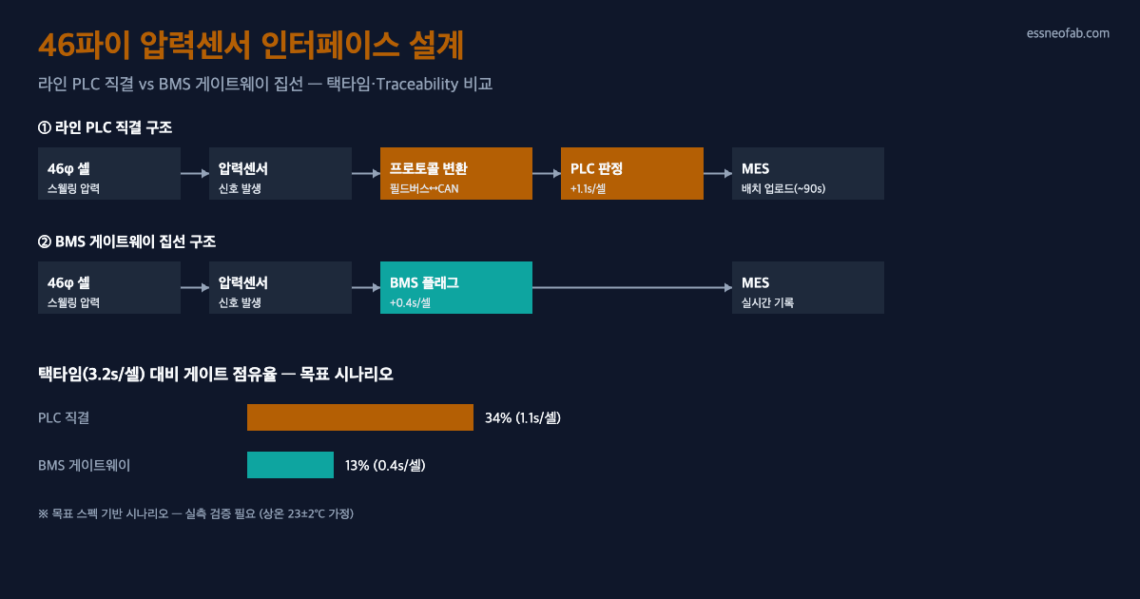
Comparing the two interface structures makes the difference clear. First, the direct line-PLC connection structure has the assembly line’s PLC directly poll the pressure-sensor signal and upload the result to the MES as a separate batch job. This structure has the advantage of low initial conversion cost, since it can reuse the existing 21700 line’s inspection-gate design as-is, but because the PLC and BMS use different protocols (the PLC typically fieldbus, the BMS typically CAN-based), an additional protocol-conversion layer is required, and this conversion delay is added directly to the per-gate judgment time.
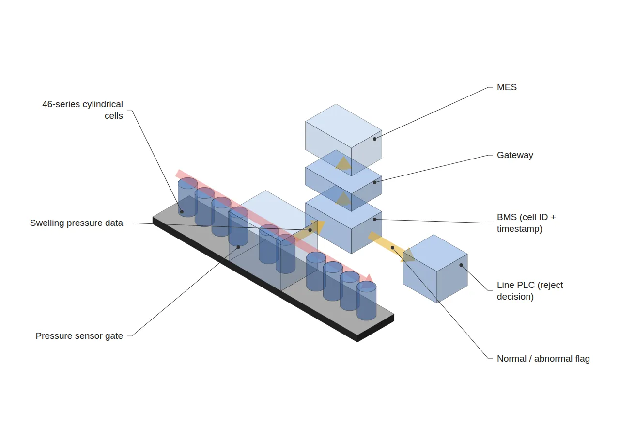
Second, the BMS-gateway primary-aggregation structure has the BMS receive the pressure-sensor signal first, timestamp it together with the cell ID, and then have the gateway transmit that data to the MES as a secondary step. In this structure, the line PLC does not need to reinterpret the pressure value itself — it only needs to receive the normal/abnormal flag already determined by the BMS to decide on rejection, so the judgment logic does not exist redundantly on both the line and BMS sides. Because the cell-ID–pressure history is combined directly at the BMS, the separate re-query step for Traceability documentation also disappears.
The practical principle this comparison implies is clear — if a new physical quantity (46-phi’s swelling pressure) is already defined as BMS-attributed at the cell-design stage, having the line design follow that attribution reduces interface redundancy. Conversely, if the line side reflexively reuses the existing PLC inspection gate, initial conversion cost is lower, but accumulated protocol-conversion delay is likely to cause losses in both takt time and Traceability.
4. Demand Background: Line-Expansion Pressure from the ESS Round-3 Bid and AI Data Centers (Trend Snapshot)
Behind the urgency of this interface-design problem is demand-side pressure. Korea Power Exchange is reportedly leaning toward expanding the size of the Round-3 ESS centralized-contract market bid — expected to be announced as early as next month — to over 1 GW (Rounds 1 and 2 were each approximately 560 MW; as of reporting on August 26, 2026). At the same time, ESS demand directed at AI data centers is growing along a separate axis — a major domestic battery maker’s first-half 2026 ESS revenue reportedly grew about 4.6-fold year-on-year, with more than KRW 3 trillion of new orders reportedly coming from hyperscaler/AI-data-center projects (as of reporting on June 30, 2026). With these two demand axes overlapping, a concurrent wave of reviews for new construction or conversion of cylindrical cell lines, including 46-phi, is likely.
However, these two figures are based, respectively, on a policy-review-stage report and a provisional first-half tally report, and may differ from the final bid announcement or confirmed second-half results. Rather than substituting them directly as grounds for a line-investment decision, it is safer to treat them as directional reference figures.
5. Target Scenario: Back-Calculating Judgment Delay, Takt Time, and Traceability
To quantitatively gauge the difference between the two structures, the following target specifications are arbitrarily set and back-calculated below. These are design-review assumptions, not measured values.
| Item | Direct Line-PLC Connection | BMS Gateway Aggregation |
|---|---|---|
| Line target takt time | 3.2 s/cell (common assumption) | |
| Gate judgment time | 1.1 s/cell (including protocol conversion) | 0.4 s/cell (flag reception only) |
| Gate share of takt time | approx. 34% | approx. 13% |
| Traceability documentation delay | up to 90 s (batch-upload wait) | real-time (cell ID – pressure recorded simultaneously) |
| Assumed initial ramp-up reject rate | 1.8% (assuming wider swelling deviation vs. 21700) | |
Measurement-condition note: the figures above are target specs assuming the 46-phi initial ramp-up phase (room temperature 23±2 °C, conveyor transport speed assumed at 12 m/min), with no measured sample. The 1.1 s/cell judgment time for the direct line-PLC-connection structure is an assumed figure that includes the delay of the fieldbus–CAN protocol-conversion layer.
Under this assumption, the BMS-gateway aggregation structure appears to lower the takt-time occupancy share from 34% to 13% and to effectively eliminate the Traceability documentation delay. This looks like a meaningful difference, but it is a scenario analysis under controlled variables, not a measured mass-production-line result. In particular, the 1.1 s/cell protocol-conversion delay can vary significantly by equipment maker and PLC vendor, and must be cross-verified against measured data from one’s own line before actual adoption.
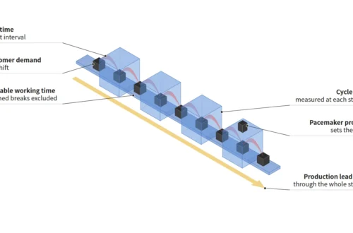
Metric definitions: Takt Time = available operating time ÷ customer-required quantity. In this article these metrics are not used interchangeably with Cycle Time or FPY.
FAQ
Q. Wouldn’t connecting the pressure sensor directly to the BMS actually slow down the line PLC’s real-time response?
A. This objection has merit. The BMS is often originally designed around a low-speed polling cycle intended for cell protection and balancing, so the concern that it may conflict with the high-speed judgment cycle a line inspection gate requires is valid. However, the structure proposed in this article does not have the BMS take on the entire judgment logic — it separates roles so that the BMS only issues the flag first, and the line PLC merely references that flag. Whether this separation, under actual mass-production conditions, stays within the BMS polling-cycle ceiling (which varies by equipment maker) requires separate verification through line-specific measurement.
Field Application Notes
| Action Item | Verification Method | Owner |
|---|---|---|
| Confirm which layer the pressure-sensor signal is attributed to | Cross-check the current line P&ID drawing to see whether the pressure sensor is wired to the PLC or the BMS | Line Design Team |
| Measure protocol-conversion delay | Stopwatch-measure the round-trip delay across the fieldbus–CAN conversion gateway section, using a sample of 10 cells (in seconds) | Controls Team |
| Check the Traceability re-query step | Confirm whether a separate batch-upload wait occurs when querying pressure history by cell ID in the MES | Quality Assurance Team |
| Check the BMS polling-cycle ceiling | Cross-check the equipment maker’s spec sheet for the BMS polling-cycle ceiling (ms) against the line’s target takt time | Purchasing/Equipment Team |
References: Patents and Trend Sources
WO2024043767A1 (cylindrical battery/BMS structure including pressure sensor, specifying the 4680 format), US12034109B2 (electrode assembly/battery/battery pack/vehicle, across the full 46-series range), report on the reviewed expansion of Korea’s ESS Round-3 centralized-contract market bid (August 26, 2026), report on new ESS orders and first-half revenue growth directed at AI data centers (June 30, 2026).
Related Reading
- ESS Assembly Line: Why Immersion Cooling Becomes a Bottleneck
- Edge AI Vision Inspection and Battery-Pack Leak Testing: How Gateway Aggregation Affects Traceability Completeness
- Introducing Robotic Automation Equipment — Where Does the Interface with Line Takt Time Break Down


One Comment
Pingback: