The 2026 Edition of NFPA 855 Changes ESS Rack Design and Traceability Documentation at the Same Time
Abstract
The 2026 edition of NFPA 855 shifts the center of gravity of ESS (Energy Storage System) safety standards from preventing ignition at the cell level to Thermal Runaway Propagation Prevention (TRPP) at the rack/container level. This revision is a line/system-engineering matter, not a problem of the battery’s own material properties, in that it brings the entire BOS (Balance of System) — including cell-to-cell spacing, detection interfaces, and cooling wiring — into the scope of design. At the same time, mandatory pre-submission of the HMA (Hazard Mitigation Analysis) and ERP (Emergency Response Plan) to fire authorities has made a Traceability system that tracks and retains design-basis data at the rack level a precondition for permitting. This article translates the TRPP requirements into interface-design variables and, using Korea’s distribution-grid ESS deployment project and US tariff/FEOC regulatory trends as reference points, presents a checklist that can be verified starting Monday morning.
1. Conclusion: TRPP Is Not a Battery Problem, It Is an Interface Problem
To state the conclusion first, the core of responding to the 2026 edition of NFPA 855 lies not in cell chemistry but in redesigning three interface variables: rack-to-rack spacing, detection-signal delay, and the documentation system. In Korea, ESS deployment projects to relieve distribution-grid connection congestion are expanding¹, while in the US, tariff increases on lithium-ion batteries and FEOC (Foreign Entity of Concern) regulations are tightening supply-chain documentation requirements². Both trends are a common signal that ESS systems are converging toward being required to provide not just “performance” but also “demonstrable safety and provenance data.”
Previously, the focus was on preventing ignition of the cell itself (Situation). However, as repeated fire investigations confirmed that completely blocking thermal runaway in a single cell has material-property limits, the regulatory focus shifted from “ignition prevention” to “propagation prevention” (Complication). What, then, must line/system designers specifically change (Question)? The answer is the simultaneous redesign of three things: cell/module spacing and barrier-material specifications, the response time of the detection-suppression interface, and a documentation system that makes all of this design basis traceable at the rack level (Answer).
2. What Is TRPP, and How Does It Differ from Existing Standards
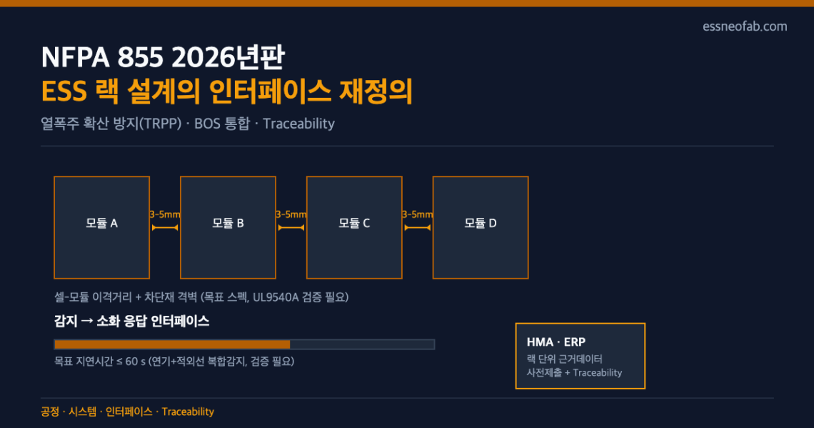
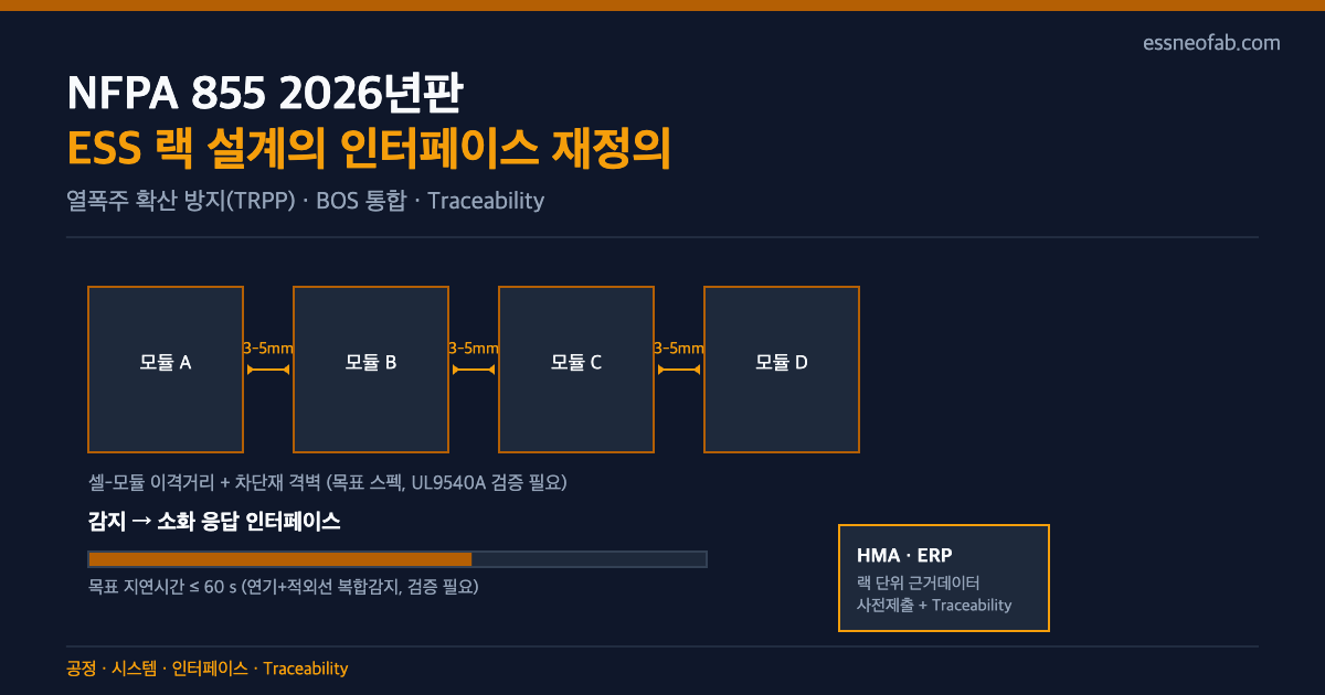
TRPP is a concept that explicitly specifies, as its safety goal, preventing thermal runaway that begins in one cell or module from propagating to adjacent cells, modules, racks, or cabinets. Where the previous approach focused on lowering the ignition probability of an individual cell, TRPP aims, on the premise that “ignition can occur,” to contain its spread at the rack level. This difference changes the design unit itself. Reviewing cell specs alone is no longer sufficient; cell-placement spacing, the thickness and material of partition barriers, and even the aisle width between racks are brought within the scope of verification.
US patent literature has long addressed this approach as well. Representative examples include a spacer structure defining minimum cell-to-cell spacing (US20100136396A1), a structure partitioning cell groups with multiple thermal barrier walls (US20100136404A1), and a pack structure combining compressive force with thermal-runaway-propagation prevention (US10873111B2). Domestically, a method of partitioning modules with barrier blocks (KR102172449B1) and a structure embedding graphite/sand/metal-powder-type thermal barrier material between tear sheets (KR102627450B1) can be found. The variable these patents commonly address — spacing (mm) and barrier-material specification — is precisely the primary parameter of TRPP design.
However, whether an individual product satisfies TRPP is, in principle, verified individually through the UL 9540A large-scale fire test, and the spacing/response-time figures presented in this article are example target specs for the design-initiation stage, not universal standard values. Actual adopted values vary by cell chemistry, pack structure, and ventilation conditions, and require separate verification.
| Design Variable | Existing Approach (Cell-Ignition-Prevention Focused) | TRPP Target Spec Example (2026-Edition Response, Verification Needed) |
|---|---|---|
| Cell-to-module spacing | Follows manufacturer-recommended value | 3–5 mm partition including barrier material + UL9540A verification |
| Module-to-module aisle width | Focused on maintenance access | Target of 150 mm or more, including ventilation/suppression access (verification needed) |
| Early-detection response time | Single-channel smoke detection | Combined smoke + infrared detection, target delay within 60 s |
| Rack temperature management | Managing normal operating range | Additional criterion for early determination of abnormal behavior via temperature rise rate (°C/s) |
3. How the Expanded BOS Scope Affects Interface Design
Another notable change in the 2026 edition is that the scope of safety review has expanded beyond internal cell/module issues to the entire BOS, including wiring, the cooling/HVAC system, and the BMS (Battery Management System). This is difficult to address under an existing division of labor in which rack-interior designers and cooling/electrical-interface designers were separate. The delay in the detection signal reaching the BMS, and the response time for the cooling system to switch from normal cooling mode to isolation mode under an abnormal condition, are now both bound into a single safety chain subject to review.
In systems adopting immersion cooling or direct cooling, whether the coolant circulation piping itself could become a pathway for fire propagation must also be reviewed together. It should be made clear that this is not a matter of the cooling mechanism of a unit device itself, but a line-integration question of how the cooling interface interlocks with the fire detection-suppression sequence.
4. Domestic and International Trend Snapshot
Domestically, a distribution-grid ESS deployment support project is underway to relieve grid-connection congestion in areas dense with renewable energy. Nine companies are building a total of 128 MW (640 MWh) of ESS across 32 distribution feeders, supporting an additional 182.4 MW of solar grid connection, and starting with the second call for proposals expected in August, expanded market entry for long-duration, long-life, high-safety batteries has been announced¹. These ESS units, distributed across individual distribution feeders, are likely to be reviewed for the TRPP/BOS requirements addressed in this article as early as the grid-connection approval stage.
Overseas, the US raised the Section 301 tariff rate on non-EV lithium-ion batteries from 7.5% to 25%, effective January 1, 2026². Combined with FEOC (Foreign Entity of Concern) regulations, this has strengthened the requirement to demonstrate country of origin and supply-chain history at the cell/module/cube level. Tariffs are a cost matter while FEOC is a contract-performance matter — different in nature — but both share the common trait of requiring cell-level Traceability data. Among US patent literature, a blockchain-based battery history-management system (US11822402B2) proposes a structure that records serial number, owner information, and supply-chain data in blocks, suggesting a direction in which fire-safety documentation (HMA/ERP) and supply-chain provenance (FEOC) — two distinct requirements — could be integrated into a single Traceability infrastructure. However, this is a conceptual design found in patent literature, and whether it can be transplanted as-is to a domestic ESS line requires separate verification.
5. Practical Implications for the Traceability System
Now that the HMA and ERP have become items subject to mandatory pre-submission to fire authorities, drafting these documents from scratch each time is not sustainable. Building a database, at the rack level, of measured spacing values, barrier-material lot numbers, and detector response-time verification history — and establishing a system that can automatically cite this basis data whenever the HMA/ERP is updated — makes a practically meaningful difference. It bears repeating that this is not a matter of the cell’s internal chemical degradation mechanism, but a system-design matter of linking rack/module-level physical-placement data with the document-management system.
FAQ
Q. If a product already passed the UL 9540A test, is there really no separate response needed for the 2026 edition of NFPA 855?
A. UL 9540A is a test that verifies whether a specific product configuration satisfies TRPP, whereas the 2026 edition of NFPA 855 separately specifies the documentation and BOS-integration requirements needed to apply that test result in the field. In other words, passing the test and obtaining installation permitting are separate procedures, and the HMA/ERP pre-submission requirement applies regardless of test-pass status. This article’s position is that test results obtained under controlled variables should be applied to field conditions with caution, and require re-verification specific to each installation environment.
Field Application Notes
Items that line/system personnel can check immediately on Monday morning are as follows.
| Check Item | Verification Method | Responsible Interface |
|---|---|---|
| Availability of measured cell-to-module spacing values | Cross-check measured mm values against the rack drawing | Mechanical Design–Quality |
| Detection-suppression response-time log | Check the delay time (s) from recent test records | BMS–Fire-Suppression-Equipment Interface |
| Cooling-system isolation-mode switching logic | Check the switching response time upon occurrence of an abnormal signal | Cooling–BMS Interface |
| Latest HMA/ERP version linked to basis data | Confirm the document revision date matches the measured-data version | Traceability System |
| Supply-chain origin documentation (overseas projects only) | Confirm FEOC-response documentation exists at the cell/module/cube level | Purchasing–Traceability |
If even one of these five items is not linked to current data, that point becomes the priority for responding to this revision. Since the specific target value for each item varies by cell chemistry and installation environment, the figures in the table above are reference specs at the design-initiation stage, and final values must be confirmed through UL9540A testing and field verification.
¹ The figures for the distribution-grid ESS deployment support project — 128 MW (640 MWh), 9 companies under agreement — are as announced on July 10, 2026. ² The Section 301 tariff increase (7.5%→25%) applies to non-EV lithium-ion batteries, effective January 1, 2026; detailed item classification requires separate confirmation.
Related Reading
- NFPA 855 (2026 Edition) Revision: ESS Safety Standards Expand From the Cell to the Entire System
- ESS Fire-Safety Kits Across 20 Sites — What the System Must Prepare
- Cell Traceability: Where Does It Break Down at the Line Level?


3 Comments
Pingback:
Pingback:
Pingback: