Grid-Forming PCS Mandate Redesigns FAT Takt Time and the BMS-PCS-EMS Interface
Abstract
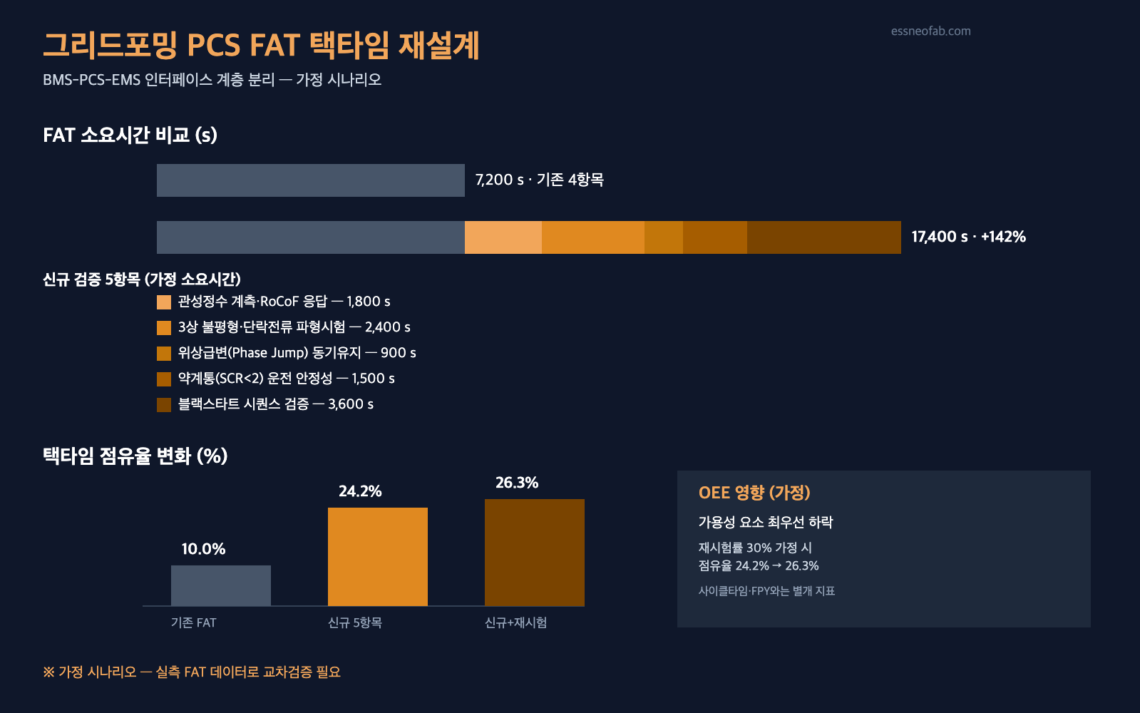
As grid-forming (GFM) inverter performance requirements become mandatory starting with long-duration BESS (Battery Energy Storage System) in the centralized-contract market scheduled for commercial operation in December 2027, five new verification stages are added to PCS (Power Conversion System) manufacturers’ Factory Acceptance Test (FAT) lines. In an assumed-scenario calculation, per-unit FAT time increases by approximately 142% over the existing baseline, pushing the takt-time share from the 10% range to the 24% range, and if retests recur, the Availability factor of OEE (Overall Equipment Effectiveness) is the first to be shaken.
At the same time, a design challenge emerges: a layer separation is needed between the grid-forming control loop, which requires sub-cycle response such as inertia constant and phase synchronization, and the EMS (Energy Management System) dispatch/BMS (Battery Management System) SOC interface, which updates on a per-second basis. This analysis is an assumption-based estimate grounded in disclosed policy and patent information, and cross-verification against actual PCS manufacturers’ measured FAT data is required.
1. Conclusion: Grid-Forming Is Not a Grid Problem — It Is a PCS Line Interface Problem
Korea’s ESS centralized-contract market has mandated grid-forming (GFM) inverter performance requirements starting with long-duration BESS scheduled for commercial operation in December 2027. Volumes are 540 MW each (onshore/Jeju) for 2027 and 2028, and 600 MW (onshore) for 2029. However, this requirement has so far been discussed only as a grid-operations-side (inertia/frequency stabilization) spec, and what changes on the PCS manufacturing/verification line side has barely been addressed.
A PCS undergoes a Factory Acceptance Test (FAT) before being connected to the grid. The five grid-forming performance requirements (providing grid inertia, robustness/fault-current supply, maintaining synchronization during phase jumps, weak-grid operation, self-start/black-start) cannot be verified through the existing grid-following PCS’s rated-output, efficiency, and protection-relay tests alone. A separate test stage must be inserted into the FAT line for each requirement.
In conclusion, the practical bottleneck of the grid-forming mandate first appears not in the grid, but in the PCS manufacturing/test line’s takt time and the redesign of the BMS-PCS-EMS interface’s data-update cycle. The two are examined in order below.
2. Background: Grid-Forming Inverter Mandate Requirements
The Ministry of Climate, Energy and Environment has finalized the related performance requirements so that long-duration BESS introduced through the centralized-contract market and entering commercial operation from December 2027 will be equipped with grid-forming functionality. While global grid-forming BESS are typically designed around a 4-hour duration, a domestic peculiarity is that Korea’s long-duration BESS requires 6 or more hours of continuous discharge.
| Category | Content |
|---|---|
| Application timing | From long-duration BESS entering commercial operation in December 2027 |
| Introduction volume | 540 MW each (onshore/Jeju) for 2027 and 2028; 600 MW (onshore) for 2029 |
| Duration requirement (domestic) | 6+ hours of continuous discharge (raised from the global standard of 4 hours) |
| Five performance requirements | ① Providing grid inertia ② Robustness/fault-current supply ③ Maintaining synchronization during phase jumps ④ Weak-grid (SCR<2) operation ⑤ Self-start (black-start) |
The control method itself also differs. A grid-following inverter passively tracks grid voltage/frequency via a PLL (Phase-Locked Loop), while a grid-forming inverter forms voltage/frequency on its own using a Virtual Synchronous Generator (VSG) model. The inertia/damping parameter structure of VSG control has also been disclosed in numerous patents (WO2020142330A1, CN205753452U). For domestic BESS, the dual central-controller/local-controller structure proposed by US11387654B2 and the vector current-control method of US12381398B2 are noteworthy prior art for reference.
3. Mechanism: FAT Takt-Time Increase and Interface Redesign (Assumed Scenario)
※ The figures below are not disclosed anywhere in news or patent literature; they are an assumed scenario set by essneofab to illustrate the calculation basis. Verification against actual PCS manufacturers’ measured FAT data is essential.
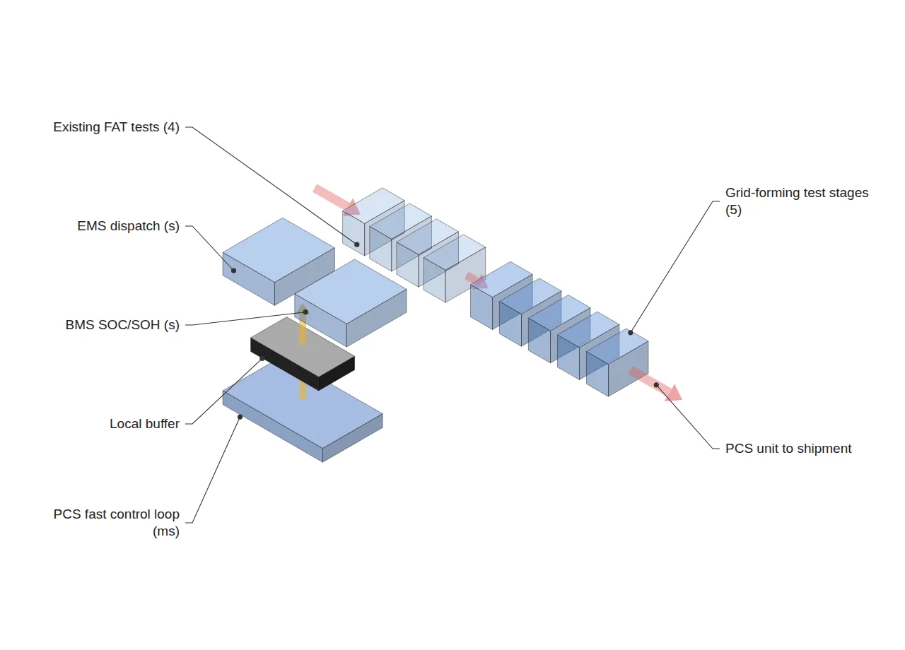
The combined time for the existing grid-following PCS’s FAT items (dielectric-withstand test, rated-output test, efficiency test, protection-relay function test) is assumed at 7,200 s (2 hours) per unit. The assumed time for each new test item required to verify the five grid-forming performance requirements is as follows.
| New test item | Performance requirement verified | Assumed time (s) |
|---|---|---|
| Inertia constant (H) measurement / RoCoF response test | ① Providing grid inertia | 1,800 |
| 3-phase unbalanced load / short-circuit current waveform test | ② Robustness/fault-current supply | 2,400 |
| Phase-jump synchronization-maintenance test | ③ Maintaining synchronization during phase jumps | 900 |
| Weak-grid (SCR<2) operation stability test | ④ Weak-grid operation | 1,500 |
| Black-start sequence verification (voltage-free start → voltage establishment → load pickup) | ⑤ Self-start | 3,600 |
| New-item subtotal | — | 10,200 |
Total new FAT time is 7,200 s + 10,200 s = 17,400 s, an increase of approximately +142% over the existing baseline (assumed scenario). Viewed from a takt-time perspective, the impact is even clearer. Setting the monthly production target at 20 units (assumed) and monthly available operating time at 25 days × 16 hours/day = 1,440,000 s (assumed):
Takt time = Available operating time / Customer required quantity = 1,440,000 s / 20 units = 72,000 s/unit
FAT time’s share of takt time rises from the existing 7,200/72,000 = 10.0% to a new 17,400/72,000 = 24.2% (assumed scenario). The issue is that the newer an item is, the lower its first-pass rate tends to be.
For items requiring control-parameter tuning, such as black-start and weak-grid tests, setting an initial retest rate of 30% (assumed) adds retest time (3,600×0.3 + 1,500×0.3 = 1,530 s), raising the FAT share to 26.3%. Of OEE’s three factors (Availability × Performance × Quality), Availability is the first to be shaken in this range, a metric distinct from cycle time or FPY.
The second bottleneck is the data-interface layer. If a grid-forming control loop requiring sub-cycle (tens of ms or less) response, such as phase-jump synchronization maintenance, is processed at the same layer as the existing EMS dispatch cycle (assumed 1,000 ms) and BMS SOC/SOH update cycle (assumed 1,000 ms), the upper interface becomes the bottleneck. Referencing the PCS performance-test system structure proposed by KR101523300B1, a reasonable design physically separates the PCS’s internal high-speed control loop (inertia/synchronization response, in ms) from the upper EMS/BMS interface (dispatch/SOC sharing, in seconds), placing a local buffer between them so the upper interface does not directly handle the grid-forming sub-cycle response. Whether this separation is needed, and the required buffer capacity, remain areas requiring field measurement verification.
4. Trend Snapshot
Fire-safety standards were also updated during the same period. UL 9540A Edition 6 (published 2026-03-13) clarifies thermal-runaway propagation test criteria across the cell-module-full-installation stages and newly adds test criteria for sodium-ion and flow batteries, and is expected to be reflected in the NFPA 855 2026 edition. The AI vision-inspection market is projected to grow from USD 32.66 billion in 2025 to USD 256.0 billion in 2035 (23% CAGR), with the shift from rule-based machine vision to deep-learning-based inspection accelerating. Both items are trends separate from this analysis’s mechanism (FAT takt time / interface layer separation) and are cited for reference only.
5. Conclusion and Implications
The grid-forming inverter mandate is a grid-stabilization policy, but its execution cost first arises on the PCS manufacturing/test line. In the assumed scenario, the range where FAT takt-time share jumps from the 10% range to the 26% range is a threshold at which PCS manufacturers must consider adding separate test stations or configuring parallel test lines. At the same time, grid-forming’s sub-cycle response requirement suggests a design principle: the BMS-PCS-EMS interface must be layer-separated into a high-speed local loop and a per-second upper dispatch layer. Both points rest on assumptions set by essneofab, and cross-verification against actual PCS manufacturers’ FAT logs and interface specifications is required.
FAQ
Q. Grid-forming requirements are already specified in overseas standards such as IEEE 2800 — can’t the domestic PCS line just apply the overseas criteria as-is?
A. No. IEEE 2800-2022 leaves response time broadly open in the 1–30 s range, to be adjusted according to TSO (grid operator) requirements, so only the existence of the test items is common, while the specific time required and pass criteria vary by country. In particular, Korea’s long-duration BESS requires 6+ hours of continuous discharge, making the test conditions themselves different from the global standard (4 hours), so FAT takt-time estimation must be performed separately based on domestic requirements.
Field Application Notes
| Check item | Action |
|---|---|
| FAT item inventory | Record the current PCS FAT test items and per-unit time (s) in full — establish a baseline before adding grid-forming new items |
| Recalculate takt time | Recalculate the takt-time share when the new FAT items are reflected, based on monthly production target and available operating time (s), to confirm the bottleneck threshold |
| Track retest rate | Separately tally the first-pass rate for each new item such as black-start and weak-grid, to confirm the actual impact on the OEE Availability factor |
| Review interface layering | Compare the EMS dispatch/BMS SOC update cycle (ms) against the grid-forming control loop’s response time to review whether layer separation is needed |
| Confirm standards updates | Share the reflection schedule for UL 9540A Edition 6 / NFPA 855 2026 edition with the purchasing/certification department |
Related Reading
- Long-Duration ESS Interface Design in the Era of Power-Grid Saturation
- Why three qualified products landed on the same duration — in DSX Ready BESS, sizing is set by the output axis
- When the Station Block Grows to 62 MWh, What Actually Shrinks Is Commissioning Labor, Not Cell Count


You May Also Like
Sebang Lithium Battery’s Simultaneous HEV Pack and ESS Module Orders — Analyzing the Cell-Inbound Interface and Cell-ID Traceability Load
46-Phi Cylindrical Cell Line Conversion: The Pressure-Sensor–BMS Interface Determines Takt Time
One Comment
Pingback: